Nest Thermostat y1 wire error e103

Tried the AC a few days ago and got “y1 wire error e103” on my NEST thermostat indicating that there was over current on the Y1 wire used to turn on the AC.

TL:DR - I replaced the contactor in the outside unit and it fixed the problem.

I used my ammeter to connect Y1 and the Red 24VAC wire. The outside unit turned on and I measured 340ma on the circuit. After having the HVAC technician troubleshoot the issue, he determine it was a problem with the NEST thermostat. I replaced the thermostat that evening and it reported the same issue. I searched Amazon and found a contactor that looked similar and had the same ratings for $15. I installed it a couple of days ago and it has worked since.

The new contactor measures 340ma also. I’m not sure why the NEST thermostat had issues with the old contactor. Maybe the old contactor current spiked when initially activated - something that my meter wouldn’t catch.

Wires used on my HVAC

Previous contactor - worked fine manually but NEST thermostat reported over current.

New thermostat installed - NEST has no issues with it.

Fail - Trashed the micro trying to tap the EEPROM bus

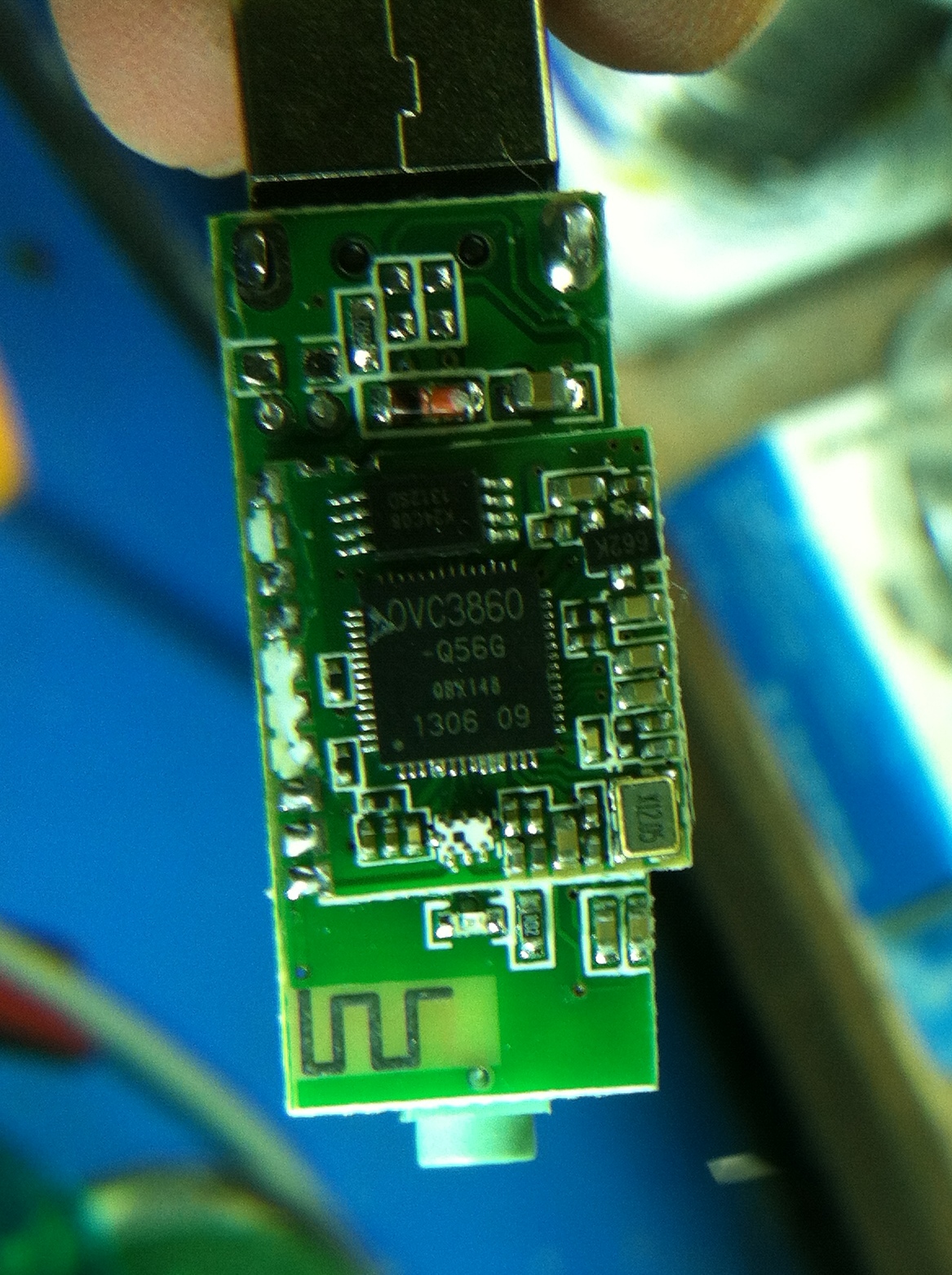
Tapping EEPROM bus fail.  I tried tapping into EEPROM serial bus so I could read and write the device ID on my Bluetooth receiver, but killed the Bluetooth processor instead.

What's wrong with this picture?have

What's wrong with this picture?have

I tied my FT232 based usb-serial adapter directly to the data and clock lines of the EEPROM while it was still on the Bluetooth PCB.  I knew I was tapping in to the circuit and could have problems if the OVC3860 micro was trying to drive the lines the same time I was.  I figured by grounding the micro's reset line, it would tri-state all of it's IO and I would be free to drive the clock and data bus.  I was mistaken.

After a few minutes of not being able to read from the EEPROM, I pulled of the tap wires and power cycled the Bluetooth receiver.  Of course, no more Bluetooth.  

My guess is that I was driving a high signal on the clock line, while the micro was driving low during reset.  The FT232 TX out line was able to source more current than the micro could take and blew out the micro.

What went wrong and the technique to do it right.

The fix is to use series resistors between the usb-serial converter and the EEPROM bus.  The series resistors limit the amount of current that can flow when the micro and the FT232 are driving different voltages.

I settled on 30 ohm resistors to limit the current about 10 ma worst case. 

  • FT232 driving 3.3 volts on to the SCL line
  • OVC3860 micro driving gnd on to the SCL line
  • Current = (Vhigh - Vlow)/ R = (3.3-0)/30 = 3.3/30 = 11 ma (or about 10 ma)

The resistor value also had to be low enough that I could still drive the bus with high and low signals within the spec for the EEPROM.  Since the SDA line is pulled high through a 5k resistor, the series resistors had to be much less than 5k.  Keeping the series resistors to less than 1/100th of the pull up meant that they would have little affect on the circuit operation.  I could have used 50 ohms, but I had 30 ohm resistors available, so I used them.


Adding Bluetooth the M&S N350 Home Intercom/Music System

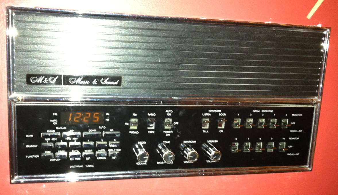
My Music and Sound N350 Master Station recently stopped working.  It was pretty sweet system... for the 20th century!  AM/FM intercom system.  What about listening to MP3's or Pandora or my favorite Pod-casts?  How about internet radio?  I had some complicated solutions like using a Rasberry Pi to stream music from the web or from iTunes sharing. 

Then I thought about Bluetooth.  With Bluetooth I could stream from any smart phone, tablet, laptop, ipod, etc. I could play internet radio stations from my phone.  Heck, I've got some old smart phones and an iPad 1.  I could  dedicate one of those as the designated streamer.

Some ideas I'm kicking around

  1. Integrate Bluetooth inside the unit
  2. Add 3.5mm jack on edge of the unit for direct connection
  3. Add USB charging port on edge of the unit for charging external players
  4. Add a dock to more permanently attach a smart phone or table
  5. Add a micro to allow remote control of the radio and intercom
  6. Integrate Bluetooth into the individual room speakers for individual listening


In case you are not familiar with it, the N350 "is a state of the art Intercom/Music Center which provides Room to Room communication throughout your house as well as furnishing AM, FM, or Auxiliary source audio."

M&S N350 Master Station

M&S N350 Master Station

Take out a couple of screws and fold it down to see an amazing rats nest of wires.


Behind the pretty panel

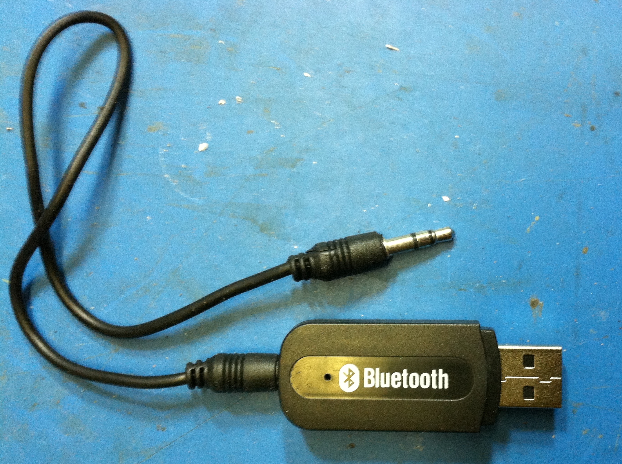
Bluetooth streaming is extremely low cost now.  I ordered a few  USB Bluetooth Music Receivers from Ebay for about $7.00 each.  They take power from USB port and have a 3.5mm jack for connection to an audio input. 

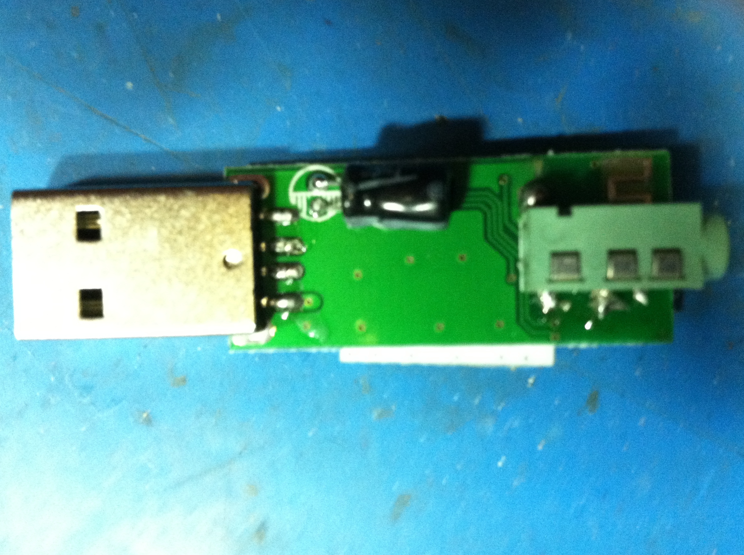
The receiver comes apart pretty easily.  It's mostly an off the shelf BT module soldered to a PCB with a few passives and an antenna.  

All I need is to tap power from the master station, add a 5 volt regulator and connect the 3.5mm jack to an audio input.  


That's going to be a problem....

That's going to be a problem....

I'm getting ahead of myself, 1st I have to fix the master station.  Right away I spotted a problem with U6.  Unfortunately, whatever took it out took out a lot more components.  All in all I found several shorted transistors and capacitors.  More on long debug process later.

Experimenting with mixing resistors

Experimenting with mixing resistors

A couple of quick notes about adding Bluetooth. Since the station is mono input, I needed to add mixing resistors from the BT receiver Left and Right Channels to the station audio input.  I picked 32 ohms to match the typical earbud input impedance.   I also need a 5 volt regulator since the only power source on the station that could be switched on/off was 15 volts.  i put the regulator and mixing resistors on a piece of perf-board and added a 3.5mm jack on the edge of the station in case i wanted to directly plug in a mp3 player or smart phone.  

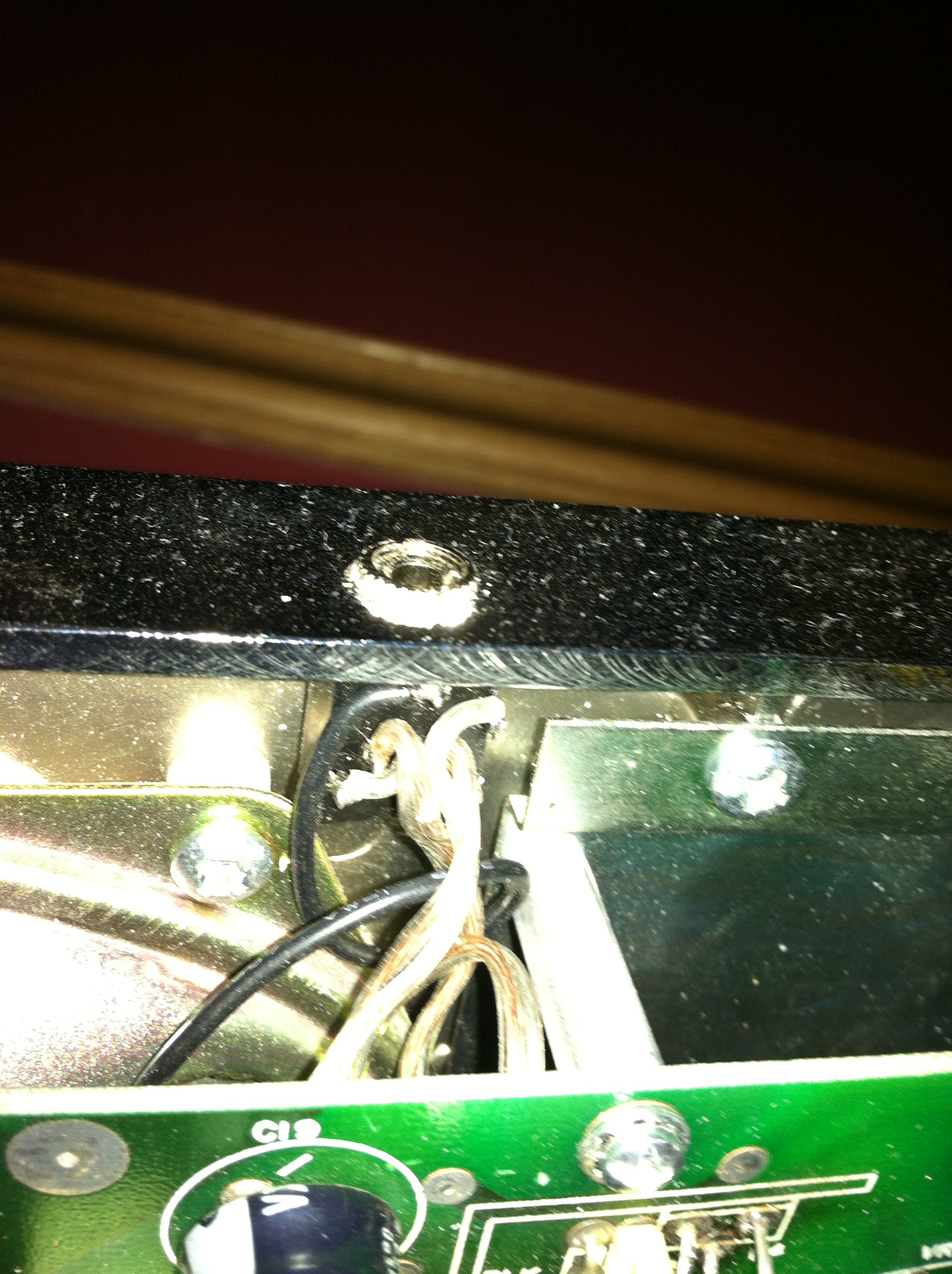
I'll add some more pics and a schematic later.  This shows the perf-board mounted on the back of the master station.  The master station front plastic (except the speaker grill) is chromed/metalized plastic.  In addition, there is a sheet of steel between the face plate and the pcb.  This is not a good situation for getting blue tooth outside of the  master station.  At first, I mounted the BT receiver so the antenna was right over the  opening for the speaker cone.  This worked great as long as my phone was directly in front of the master station.  I had about 20 feet of range, unless i moved to the side.   

I cut out the steel sheet and the portion of the plastic face plate behind the decorative speaker grill which is larger than the  speaker (thank goodness!).    I now have a 20' range no matter where I am in the room.


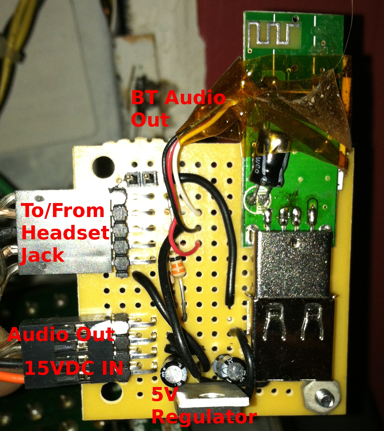
M&S 350 Voltage Regulator and Audio Interface for USB Powered Bluetooth Receivers

M&S 350 Voltage Regulator and Audio Interface for USB Powered Bluetooth Receivers

This adapter provides 5 volt regulated USB ports for power/charging and provides Bluetooth and panel mount audio inputs to the 350 intercom.

  • Power Path:
    • P2 provides +15 volt input from the 350 "Phono Enable" line.
    • U1 regulates voltage to +5 volts
    • The J1 USB connector on the adapter provides +5 volts to the Bluetooth module.  No data is supported across the USB port.
    • +5 volts is also provided to P2 through P1 enable jumper for an optional panel mount USB port.
  • Audio Path:
    • To save space, I used jumper wires to connect to the Bluetooth audio output via P4-P6.
    • Bluetooth audio is passed through the  panel mount  stereo jack via P3 connector. 
    • When the panel mount stereo jack is empty, the Bluetooth audio is passed back to the P3 connector.
    • When the panel mount stereo jack has an external source plugged in, the Bluetooth audio circuit is interrupted and the external audio is passed back to P3
    • The audio from P3 is STEREO, but the 350 only supports MONO so I had to mix the left and right channels into a single mono channel.  I used two resistors since the phono input is an op amp.  I started with 33 ohm values since most MP3 headphones input impedance is around 30 ohms.  When I tested the circuit, it sounded good and seemed to match the volume level of the 350, so I stuck with the 33 ohm resistors.
    • The MONO audio is passed to the 350 "Phono Input" via P2.

Quick test to find a failed transistor

I've been trying to fix my home intercom system.  It fails by blowing fuses so I figured one or more components had failed short.  Boy was I wrong lots of shorted components including several transistors. 

It's pretty easy to test a bipolar transistor with a DVM in diode test mode.  You don't need to know whether its NPN or PNP so it's pretty quick.

Quick test to see if a transistor is bad. This works for most NPN and PNP transistors that have failed with a short.

Published an Android App today

My better half exclaimed ​"You finished something" when I told her Whitenoise was in the Google Play Store.  She's used to my projects getting only so far before a new one takes over my attention.  My try at Android App creation likely would have fizzled out if I had not found a motivation a few months ago to keep it going...

​A few years ago I ran across an Android Development tutorial post on my favorite site hackaday.com and I was interested.  Last year I finally decided to give i a try.  By that time the tutorial was out of date and I had a lot of trouble getting everything installed until I found my way to the android developer site (getting started). 

​The development environment is pretty easy to use once everything is set up (eclipse, Android SDK and ADT Plugin).  It's set up to create a working "Hello World" app every time you create a new android application with no coding required.  There's even an "Android Virtual Device" which is a mini-smart phone that pops up on your screen to run your app on.   You can even plug a droid into the USB port and download the app directly to it for debugging. Of course I had issues, but a quick Google search found someone with the same problem and and a solution.

​I didn't make much progress until I found an amazing tutorial series by thenewboston.   All of the tutorials are 5-10 minutes long so its easy to follow along and quick to replay when I missed something.

After a few months, I felt myself losing interest since I didn't have a motivation.   We were on a trip and my wife had trouble sleeping because it was too quiet and every little noise woke her up.  I pulled up a white noise app on my phone, but it stopped after a couple of minutes.  That's when it hit me that I could make a white noise app myself instead of just installing another one for free.  

​Finally motivated I set to work.  I had lots of stops and starts going down each path until finding that something didn't work that way, or I didn't like the results.  I had to figure out how to generate white noise continuously instead of stopping after a couple of minutes.  Then I had to handle some of the different lifecycle states the app has to handle when turning the phone from portrait to landscape, hitting the back button or when a phone call comes in.  ​Then I wanted to add some pizzazz since the user interface was pretty simple so I decided to add an analog clock face and a slider to dim the display when you are sleeping.

​Finally the app was complete and it was time to put it in the play store.  This required a little Marketing (Ahhhhh!). Rudimentary by any standards, but I'm an engineer so it took a few days to come up with a passable description, some screen shots and a web page (required to publish an app in the play store). 

​In the end the app provided the motivation to create a website (openloopengineer.com) and start a blog,  Two things I've wanted to do for the past couple of years.  Hopefully motivation to expand the website and post to the blog will continue.

Thanks for reading

​Create Android Application Project

​Eclipse with Android SDK and ADT installed

​AVD Pop-up Smart Phone to test with

​AVD Running Hello World with no coding